



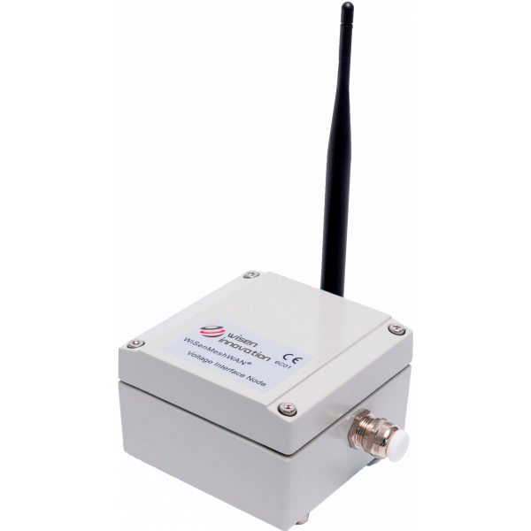

Voltage Interface Node
Voltage-type sensors with Vin = 1.8 V / 2.5 V / 3.3 V / 5.0 V, required current ≤ 100 mA and sensor output signal (Vout) ≤ sensor input voltage (Vin).
Request more information
Voltage Interface Node
The WiSenMeshWAN® system provides dynamic and autonomous wireless data acquisition from geotechnical sensors using state-of-the-art technology. The automated measurement of geotechnical sensors, using long-range wireless radio nodes and a SmartGateway, allows users to focus on more demanding tasks instead of manually acquiring and recording data.
WiSenMeshWAN® sensor nodes are transmitters and receivers that create a self-forming dynamic radio mesh network that sends data to a SmartGateway. Users have complete remote control of the system through direct, triggered or scheduled changes, enabling dynamic measurements and automated reporting.
| Type 6C01 – WiSenMeshWAN® Voltage Interface Node | |
|---|---|
| Basic features | |
| Battery power supply | 1 primary 3.6 V type D lithium battery (ER34615) |
| Accuracy cut-off voltage | 2.7 VDC |
| Mesh network cut-off voltage | 2.1 VDC |
| Battery connection | Standard aluminium battery holder |
| Operating current (DC) | Max. 210 mA |
| Local storage | Minimum of 450 messages during mesh connection |
| Dimensions (L x W x H) | Interface node: 100 x 100 x 60 mm |
| Weight | 0.6 kg |
| External sensor size and weight | Depends on the connected sensor (external cable length ≤ 1.0 m) |
| Cable glands | 1 x EMC-CMA12 for external sensor connection |
| Cable connection | Spring terminal |
| Main sensor | |
Sensor type: Signal output range (0 to Vcc_Out) / Input voltage (Vcc_Out) at max. 100 mA
Note: External sensor power-on time: 1 second before sampling. Confirm the sensor stabilisation time before use. | |
| Accuracy | 0.05% F.S. (full scale) |
| Resolution | 0.18 mV |
| Standard system parameters | |
| Temperature | Range: -40 to 85°C; accuracy: ±1°C; resolution: 0.1°C |
| Voltage | Accuracy: ±0.1 V |
| WSN interface | |
| Wireless mesh interface | WiSenMeshWAN® protocol |
| Sampling range selection | |
The physical “Vcc_Out Hardware Switch” is used to:
Example: For model 6C01, Vcc_Out must be set to 2.5 V to power an EC-5 soil moisture sensor and allow the node to sample signals between 0 and 2.5 V. Warning: For other sensors, review their specifications before configuring the node. | |
| Vcc_Out output switch configuration | |
| Switch position | Output voltage (Vcc_Out) |
| 0 (default) | 1.8 V (default) |
| 1 | 2.5 V |
| 2 | 3.3 V |
| 3 | 5.0 V |
The sensors are plug-and-play and operate straight out of the box through a self-configuring radio network. Multiple interface options enable integration with third-party sensors from leading geotechnical manufacturers using analogue, digital and vibrating-wire interfaces.
Designed for up to 10 years of maintenance-free operation, the units have an IP65 or higher protection rating and feature internal power supplies and radios. Thanks to their robust industrial enclosures, they can be installed in multiple ways to meet the different requirements of monitoring projects.


